
TL;DR This article on Failure Mode and Effects Analysis explains this powerful and commonly used family of techniques. You can access this webinar (and all the others) here.
I have used FMEA and related techniques on many programs, and it can produce powerful results quickly and cheaply. Recently, I’ve seen some criticism of FEMA on social media. However, I’m convinced that this is only clickbait. The secret of success is to understand what a technique is good for – and not – and to apply it well. It’s as simple as that!
This article covers:
- A description of the technique, including its purpose;
- When it might be used;
- Advantages, disadvantages and limitations;
- Sources of additional information;
- A simple example of an FMEA/FMECA; and
- Additional comments.
I’ve added some ‘top tips’ of my own based on my personal experience in the industry.
Top Tip
In this article, I have used material from a UK Ministry of Defence guide, reproduced under the terms of the UK’s Open Government Licence. I have rewritten the very dull source material to make it more readable!
A Description of the Technique, Including Its Purpose
Failure modes and effects analysis (FMEA) was one of the first systematic techniques for failure analysis. It was developed in the United States military (Military Procedure MIL-P-1629, titled ‘Procedures for Performing a Failure Modes, Effects and Criticality Analysis’, November 9, 1949) as a reliability evaluation technique to determine the effect of system and equipment failures. Failures were classified according to their impact on mission success and personnel, equipment, and safety. In the 1960s, it was used by the aerospace industry and NASA during the Apollo program. More and more industries – notably the automotive industry – have seen the benefits to be gained by using FMEAs to complement their design processes.
This qualitative technique helps identify failure potential in a design or process i.e., to foresee failure before it actually happens. This is done by defining the system that is under consideration to ensure system boundaries are established, and then by following a procedure, which helps to identify design features or process operations that could fail. The procedure requires the following essential questions to be asked:
- How can each component fail?
- What might cause these modes of failure?
- What could the effects be if these failures did occur?
- How serious are these failure modes?
- How is each failure mode detected?
- What are the safeguards in place to protect against accidents resulting from the failure mode?
As always with safety analyses, the more precisely you can answer these questions (above), the better the results you will get.
Top Tip
As an aid in structuring the analysis and ensuring a systematic approach, results are recorded in a tabular format. Several different forms are in use, and the form design can be tailor-made to suit the particular requirements of a study. Examples of forms can be found in several standards (links below).
Make the form support the flow of the process, left-to-right, then top-down!
Top Tip
The FMEA analysis can be extended if necessary by characterizing the likelihood, severity, and resulting levels of risk of failures. FMEAs that incorporate this criticality analysis (CA) are known as FMECAs. A FMECA is an analytical quantitative technique that ranks failure modes according to their probability and consequences (i.e., the resulting effect of the failure mode on the system, mission, and personnel). This technique is referred to as a “bottom-up approach” as it starts by identifying the potential failure modes of a component and analyzing their effects on the whole system. It can be quite complex depending on how the user drives the technique.
We should note that the FMECA does not provide a model by which system reliability can be quantified. Hence, if the objective is to estimate the probability of events, a technique that results in a logic model of the failure mechanisms must be employed, typically a fault tree and/or an event tree.
Reliability Block Diagrams, or for repairable systems, Markov Chains can also be used.
Top Tip
A FMEA or FMECA can be conducted on either a component or a functional level. A functional FMEA/FMECA only covers hardware aspects, but a functional FMEA/FMECA can cover all aspects of a system. For either approach, the general principle remains the same.
When it Might be Used
FMEA is applicable for any well-defined system, but is primarily used for reviews of mechanical and electrical systems. It can be used in many situations, for example, to assess the design of a product in terms of what could go wrong in manufacturing and in-service as a result of the weakness in the design. We can also use it to analyze failures in the manufacturing process itself and during service. It is effective for collecting information needed to troubleshoot system problems and improving maintenance and reliability of plant and equipment (defining and optimizing), as it focuses directly and individually on equipment failure modes.
It’s fair to say that you need a design, on which to perform a FMEA. Pre-design you could use Functional Failure Analysis (FFA) instead.
Top Tip
The FMECA technique is best suited for detailed analysis of system hardware, and should preferably be carried out by the designer in parallel with system development. This will not only speed up the analysis itself, but also force the design team to think systematically about the failure characteristics of the system. The primary use of the FMECA is in verifying that single-component failures cannot cause a catastrophic system failure.
There are a number of areas today in which the use of FMECA has become mandatory to demonstrate system reliability. Examples of such requirements are in the classification of Dynamically Positioned (DP) vessels and in a number of US military applications for which MIL-STD documents apply.
Advantages, Disadvantages, and Limitations
Advantages
- It is widely used and well-understood, and easy to understand and interpret
- It can be performed by a single analyst or more if required
- Qualitative data about the causes and effects can be incorporated into the analysis
- It is systematic and comprehensive, and should identify hazards with an electrical or mechanical basis
- The level of detail incorporated can be varied to suit the analysis
- It identifies safety-critical equipment where a single failure would be critical for the system
- Even though the technique can be quite time-consuming it can lead to a thorough understanding of the system being considered
Disadvantages
- The technique adopts a bottom-up approach, and if conducting a component-level FMEA or FMECA, this can be boring and repetitive
- The benefit gained is dependent upon the experience of the analyst or the group.
- It requires a hierarchical system drawing as the basis for the analysis, which the analyst usually has to develop before the FMEA process can start
- It is optimised for mechanical and electrical equipment, and does not apply easily to Human Factor Integration, procedures, or process equipment
- It is difficult for the technique to cover multiple failures, as equipment failures are generally analysed one by one; therefore, important combinations of equipment failures may be overlooked
- Most accidents have a significant human or external influence contribution, and these are not a usual failure mode with FMEA
- More than one FMEA may be required for a system with multiple modes of operation
- Due to its wide use, there can be a temptation to read across data from ARM or ILS projects where, for example, the fault-tree technique has been used. As a consequence, the safety perspective can be lost as human error has been excluded and the focus has been solely on determining faults and not on more far-reaching safety issues
- Perhaps the worst drawback of the technique is that all component failures are examined and documented, including those that do not have any significant consequences.
- For large systems, especially those with a fair degree of redundancy built into them, the amount of unnecessary documentation is a major disadvantage. Hence, the FMECA should primarily be used by designers of reasonably simple systems. It should, however, be noted that the concept of the FMECA form can be quite useful in other contexts, e.g., when reviewing an operation rather than a hardware system. Then the use of a form similar to the FMECA can provide a useful way of documenting the analysis. Suitable columns in the form could, for example, include: operation, deviation, consequence, correcting or reversing action, etc.
ARM = Availability, Reliability, Maintainability
Top Tip
ILS = Integrated Logistic Support (or logistics engineering)
Sources of Additional Information, such as Standards, Textbooks, and Websites
HSE Website – Marine Risk Assessment, Offshore Technology Report 2001/063
IEC 60812:2018 Failure modes and effects analysis (FMEA and FMECA)
As always, Understand your Standard (what it was designed to do) to get the best out of it!
Top Tip
A Simple Example of an FMEA/FMECA
An example extract from an FMEA of a ballast system is shown below. This can be found in the HSE Marine Risk Assessment Report. The column headings are based on the US Military Standard Mil-Std 1629A, but with modifications to suit the particular application. For example, the failure mode and cause columns are combined. The criticality of each failure is ranked as minor, incipient, degraded, or critical.
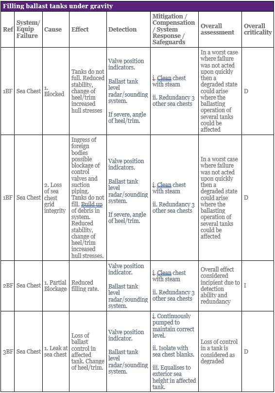
To properly understand these results you need to know how a Sea Chest works (see context here). Otherwise the example just shows what kind of output a FMEA can produce.
Top Tip
Additional comments
Failure Modes and Effects and Criticality Analysis (FMECA) is an analytical QRA technique, used by ARM and ILS systems engineers, most commonly and effectively at the late design, test and manufacture stage of a project. It requires the breakdown of the system into individual components and the identification of possible failure modes or malfunctions of each component, (such as too much flow through a valve). Referred to as a bottom-up approach, it starts by identifying the potential failure modes of a component and analyzing their potential effects on the whole system. Numerical levels can be assigned to the likelihood of the failure and the severity or consequence of the failure.
Note: It is important to recognize that FMEA/FMECA Standards have different approaches to criticality. Failure mode severity classes 1 – 5 for Standards MIL1629A and ARP926A go from Class 1 being the most severe (e.g. loss of life) to Class 5 being less severe (i.e. no effect), whereas BS 5760 deals with criticality in the opposite direction where Class 5 is the most severe.
Note that FMECA for ARM/ILS looks at availability or mission criticality, not safety criticality. A FMECA for safety will have a different focus.
Top Tip
Software:
- Isograph;
- Reliability Work Bench;
- Reliasoft;
- Microsoft Excel.
These are not recommendations!
FMEA/FMECA tables for complex systems can run to hundreds of pages, so good tool support is essential.
Top Tip
Failure Mode Effects Analysis: Have You Used This Technique?
Back to the Safety Assessment topic page.
Meet the Author

Learn safety engineering with me, an industry professional with 25 years of experience. I have:
•Worked on aircraft, ships, submarines, ATMS, trains, and software;
•Tiny programs to some of the biggest (Eurofighter, Future Submarine);
•In the UK and Australia, on US and European programs;
•Taught safety to hundreds of people in the classroom, and thousands online;
•Presented on safety topics at several international conferences.